A NOTE FOR STUDY REPORT
Reset Purpose
1.Force the ASIC design into a known state for simulation2.Every flip-flop in an ASIC should be restable whether or not it is required by the system
General flip-flop coding style notes
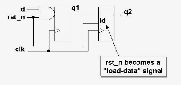
Should not mix resetable FF with follower FF (FF with no reset) in the same procedural block or process.Example for bad Verilog coding style to model dissimilar FF

Where q2 can only load data when rst_n=1(means DFF is required extra load-data control in DFF)
Bad coding style yields a design with an unnecessary loadable flip-flop
The correct way is to put dissimilar FF in the separate always block as shown below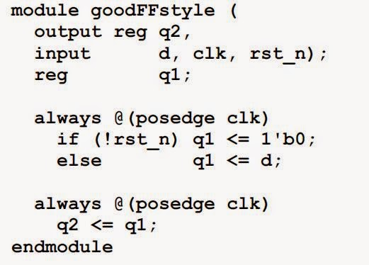

Good partitioning with no extra logic, q2 is loaded on every posedge clk
Synchronous resets
The coding style to model the reset should be an if/else priority style with the reset in the if condition and all other combinational logic in the else sectionIf this style is not strictly observed, that may cause two problems
1.In some simulators, based on the logic equations, the logic can block the reset from reaching the flip-flop =>這是由於優先權的問題所產生
2.The reset could be a “late arriving signal” relative to the clock period, due to the high fanout of the reset tree =>high fanout的多傳遞訊號可能會造成延遲問題
Correct way to model a FF with synchronous reset

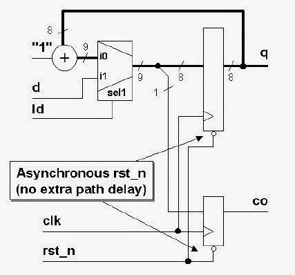
Below shows an code and implementation for synchronous reset as part of a loadable counter with carry out


One problem with synchronous resets is that the synthesis tool cannot easily distinguish the reset
signal from any other data signal.The synthesis tool could alternatively have produced the circuit below

This is functionally identical to above circuit. The only difference is that the reset AND-gates are
outside the MUX.Now, consider what happens at the start of a gate-level simulation. The inputs
to both legs of the MUX can be forced to 0 by holding rst_n asserted low, however if ld is
unknown (X) and the MUX model is pessimistic, then the flops will stay unknown (X) rather
than being reset
=>如果load unknown,reset無法正常使用
Advandatages of synchronous reset
1.Synchronous reset logic will synthesize to smaller flip-flops(但是在現在的設計如此龐大,此優點比較沒有重要性)
2.Synchronous resets generally insure that the circuit is 100% synchronous
3.Synchronous resets insure that reset can only occur at an active clock edge. The clock works as a filter for small reset glitches.
4.In some designs, the reset must be generated by a set of internal conditions. A synchronous reset is recommended for these types of designs.(因為combinational電路容易產生glitch)
5.By using synchronous resets,flip-flops can be used within the reset buffer tree to help the timing of the buffer tree keep within a clock period
Disadvandatages of synchronous reset
1.Synchronous resets may need a pulse stretcher to guarantee a reset pulse width wide enough to ensure reset is present during an active edge of the clock.2.A synchronous reset will require a clock in order to reset the circuit. This may be a problem in some case where a gated clock is used to save power.
3.A potential problem exists if the reset is generated by combinational logic, during sumulation, the reset can be masked by X, and most simulators will not resolve some X-logic conditions and therefore block out the synchronous reset.
Note that this problem is not so much what type of reset you have, but whether the reset signal is easily controlled by an external pin
Asynchronous reset
The reset is part of the sensitivity list, below show the correct way to model asynchronous reset FF.
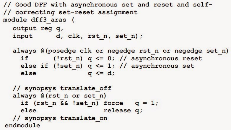
modeling verilog flip-flops with asynchronous reset and asynchronous set
The simulation model of a flip-flop that includes both an asynchronous set and an asynchronous reset in Verilog might not simulate correctly without a little help from the designer.
Note that the problem is only a simulation problem and not a synthesis problem (而且這種設計很少見到)

set應該要在reset remove的同時立刻active,但是由於不會被trigger所以必須要強制進入set的模式,以下為v code寫法
Advantages of asynchronous reset
1.Using an asynchronous reset, the designer is guaranteed not to have the reset added to the data path.below shows the code and implementation of loadable counter with asynchronous reset

clock present.
Disadvantages of asynchronous reset
1.For DFT, if the asynchronous reset is not directly driven from an I/O pin, then the reset net fromthe reset driver must be disabled for DFT scanning and testing
2.Static timing analysis is very difficult to do with designs using
asynchronous resets
3.The biggest problem with asynchronous resets is that if the asynchronous reset is released at or near the active clock edge of a flip-flop, the output of the flip-flop could go metastable
4.Another problem that an asynchronous reset can have, depending on its source, is spurious resets
due to noise or glitches on the board or system reset
Asynchronous reset problem
As shown below, an asynchronous reset signal will be de-asserted asynchronous to theclock signal. There are two potential problems with this scenario:
(1) Violation of reset recovery time
(2) Reset removal happening in different clock cycles for different sequential elements.

clock signal goes high again.Missing a recovery time can cause signal integrity or metastability problems with the registered data outputs.

Reset removal traversing different clock cycles
When reset removal is asynchronous to the rising clock edge, slight differences in propagation
delays in either or both the reset signal and the clock signal can cause some registers or flip-flops to exit the reset state before others.
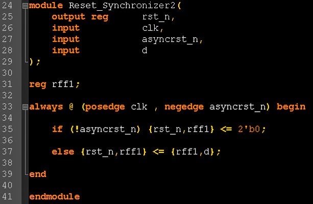
Reset synchronizer
Guideline: EVERY ASIC USING AN ASYNCHRONOUS RESET SHOULD INCLUDE A
RESET SYNCHRONIZER CIRCUIT!!
Without a reset synchronizer, the usefulness of the asynchronous reset in the final system is void
even if the reset works during simulation.
The reset synchronizer logic is designed to take advantage of the best of both
asynchronous and synchronous reset styles.

Using two FF to remove any metastability, the code and wave form for the reset synchronizer circuit


Reset distribution tree
The reset distribution tree requires almost as much attention as a clock distribution treeUnlike clock signals, skew between reset signals is not critical as long as the delay associated with any reset signal is short enough to allow propagation to all reset loads within a clock period and still meet recovery time of all destination registers and flip-flops
In order to help speed the reset arrival to all the system flip-flops, the reset-driver flip-flop is
clocked with an early clock as shown below

Reset-glitch filtering

Multi-clock reset issues
For a multi-clock design, a separate asynchronous reset synchronizer circuit and reset distribution tree should be used for each clock domainThis is done to insure that reset signals can indeed be guaranteed to meet the reset recovery time for each register in each clock domain
Depending on the constraints of the design, there are two techniques that could be employed
(1) non-coordinated reset removal, and
(2) sequenced coordination of reset removal
non-coordinated reset removal

remove沒有先後順序,只要在差不多時間remove即可
sequenced coordination of reset removal
For some multi-clock designs, reset removal must be ordered and proper sequence. For this typeof design, creating prioritized asynchronous reset synchronizers
Required to insure that all aclk domain logic is activated after reset is removed before the bclk
logic, which must also be activated before the cclk logic becomes active.

有先後順序,每個reset的remove都需要看前一級remove的情形,以下為sequenced coordination of reset removal的verilog code